New energy vehicle drive motor system linkage training platform

Model No.︰XL-EVA0103
Brand Name︰XL
Country of Origin︰China
Unit Price︰US $ 9859 / pc
Minimum Order︰1 pc
Product Description
Ⅰ.Product Overview:
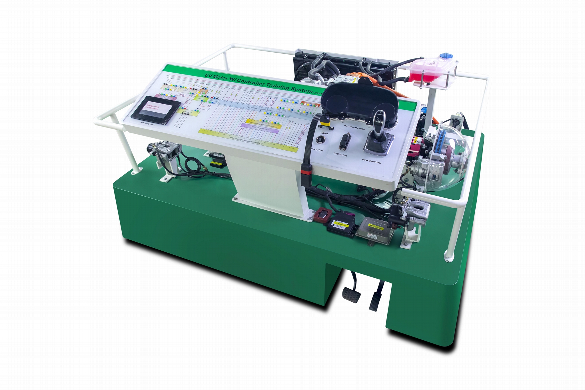
The platform adopts BYD E5 Battery electric vehicle power system, including electric power motor assembly, drive and transmission system components, gear controller, energy recovery system, braking system, front left and right Steering Knuckle assembly, Driver Shaft, brake and auxiliary mechanism, electronic accelerator pedal, detection panel, etc., It can be used to start, accelerate, decelerate and other conditions of the battery electric power system practice operation. The composition structure and working process of the battery electric power system are truly displayed. It is suitable for the teaching needs of battery electric power system maintenance training.
Ⅱ.Functional Features:
1. The platform adopts the disassembled drive motor system of BYD E5 original model, fully demonstrating the composition structure and working process of the battery electric vehicle drive system.
- Show , learn, and practice the following knowledge points: the type, structure and working principle of permanent magnet synchronous motor, the main technical indicators of the motor, the output characteristics of the motor, the structure and principle of the rotating transformer, the fault detection of the rotating transformer, the principle of the inverter, the static and dynamic parameters of the power triode IGBT, etc.
- The original instrument panel are equipped to display the parameter changes of power transmission process, speed, electric control system fault indicator and other parameters in real time.
- The training platform is equipped with accelerator pedal and brake pedal devices, which can facilitate the acceleration, deceleration and stop working of the battery electric vehicle drive system.
- Configure the intelligent fault assessment function: it mainly consists of two independent systems, the teacher fault setting terminal and the student answer terminal, which are installed on the mobile terminal. Teachers can use mobile teaching terminal to connect with the fault setting module of integrated teaching AIDS for fault setting. After the fault setting is completed, students can use the mobile learning terminal to carry out the examination and answer questions. After the examination, the score is automatically stored in the module, which is convenient for the teacher to query the score of each student.
- In order to facilitate the identification and measurement of sensors and actuators, and to reduce plug damage caused by plug removal and insertion of sensors and actuators while restoring the detection scene of the real car, a detection end ≥5cm is required to be placed in parallel beside the plug of the original car wiring harness.,and the detection end is made of transparent Acrylic material by laser engraving and flat jet painting, with the same shape as the plane shape of the original car plug. The measuring end adopts a special detection terminal, and marks the number of the measuring Angle and the name of the sensor and actuator. The electrical signals of each sensor, actuator and control unit pin can be detected directly on the measuring terminal, such as resistance, voltage, current and frequency signals. With the help of multimeter and oscilloscope, the parameter changes under various states can be detected in real-time.
- The Training platform frame is assembled by European standard aluminum profile , solid and reliable never change color. There are 4 casters installed at the bottom of the platform frame ,so it is flexible movement, while the casters with self-locking device, so position can be fixed.
- OBD-II diagnostic socket is installed on the panel of the training platform, which can be connected to a special car decoder to carry out self-diagnostic functions such as fault code reading, clearing and data stream reading for the control unit.
- The panel of the training platform is printed with circuit diagram and configured with detection port. With the help of multi-meter and oscilloscope, the parameter changes under various states can be detected in real time.
- The Training platform is equipped with training instructions manual.
Ⅲ.Product composition.
The Training Platform is composed of BYD E5 permanent magnet synchronous motor, fixed gear ratio transmission, instrument panel, diagnostic port, detection panel, accelerator pedal, brake pedal device, movable frame made of aluminum material, etc.
Ⅳ.Training Purpose.
- Understand the actual structure, circuit and working principle of BYD E5 motor drive system, and learn to identify the motor and motor controller nameplate;
2, understand the power transmission process, motor speed, electronic control system fault indicator light and other parameter changes;
3, learn the different functional modules of the motor controller, and the regulation and management of the motor controller under different load conditions;
4, show the internal operation of the motor under the corresponding control (acceleration, deceleration, backward);
5. Understand the high and low voltage lines in the drive motor system and their functions;
6, master BYD E5 power motor basic inspection and maintenance methods;
7, master the detection method of motor temperature sensor, motor speed sensor and rotary converter ;
8, master the insulation test method of power motor;
9, master the detection methods of drive motor control system high voltage and low voltage lines ;
10.Master the noise detection method of power motor (need to be equipped with noise detector)
11. Master the working principle, testing and maintenance methods of the cooling system of the motor drive system;
12, master the use of vehicle analyzer method, read the power motor and motor drive system data flow, fault code, fault code clearance;
13, master the disassembly and assembly method of the motor (pay attention to high voltage safety operation specifications);
14, show the motor data changes and ECU, motor controller response principle;
15. Fault diagnosis of the drive motor system;
Payment Terms︰ TT
Product Image